
Automotive Oscilloscope Basics: The First Tests Every Diagnostic Technician Should Learn
TL;DR
An automotive oscilloscope search usually means you’re ready to move past “symptom guessing” and start diagnosing with evidence. Instead of relying on vehicle reports, a scope shows what a circuit or component is doing in real time, so you can prove whether a signal is healthy, unstable, delayed, noisy, or failing under load.
If you searched automotive oscilloscopes, you’re likely ready to strengthen your diagnostic process with real-time electrical evidence. A scope doesn’t replace a scan tool, it adds another layer of clarity by showing what a circuit or component is actually doing at the moment. That’s especially valuable on modern vehicles, where a concern can be intermittent, load-related, or subtle enough that a trouble code never sets.
In this article, you’ll learn a practical, beginner-friendly workflow: start by confirming baseline electrical health, then capture the most common signals used in everyday diagnostics, and finally use measurements and comparisons to interpret results correctly.
We’ll focus on the first tests that deliver the most leverage early on, battery/starting/charging checks, alternator ripple, crank/cam correlation, injector control signals, and ignition primary testing, along with common mistakes to avoid when reading waveforms.
Where a Lab Scope Fits in Diagnosis
Scope vs scan tool is not an “either/or”
A scan tool is excellent at reading what modules say is happening: diagnostic trouble codes, data parameters (PIDs), readiness status, and commanded states. The limitation is that module data is still an interpretation. It can be delayed, filtered, or incomplete, and some failures occur so quickly (or intermittently) that a module never flags them.
That’s where an automotive oscilloscope becomes essential. A scope shows what electricity and electronics are doing in real time, including:
- Voltage and current behaviour
- Frequency and duty cycle
- Timing relationships between signals
- Noise, dropouts, and distortion
A practical way to think answer “when is a scope better than a scan tool?” A scope is better when you need to see what a circuit or component is actually doing in real time, especially for load-dependent and intermittent electrical faults that may not set a code.
Why Guided Tests Help Beginners Learn Faster
If you’re new to waveform diagnostics, still in your auto mechanic course, most early mistakes are about setup. A scope can produce confusing results even when the circuit is fine if the timebase is wrong, the voltage range is inappropriate, the trigger is unstable, or the probe method doesn’t match the circuit.
Guided tests reduce that learning friction by standardizing the basics. Instead of guessing your settings, you’re starting from a configuration built for the test you’re performing. That means fewer “bad captures,” more useful waveforms, and faster progress.
You can still become a strong diagnostic technician without guided tests, but they do help you build habits that matter long-term: correct connections, repeatable setup, and consistent comparison.
Set up Fundamentals for Reliable Scope Results
A scope, you control what gets captured. Before you move into component testing, anchor yourself in three fundamentals that prevent most beginner misreads.
1) Capture the right time window for the event
A millisecond injector event will look meaningless if it’s squeezed into a long sweep. At the same time, a battery cranking event can’t be understood if your capture window is too narrow. Guided tests often choose a workable starting point, but as you improve, you’ll increasingly adjust timebase and scaling manually based on what you’re trying to see.
Quick check before you hit record:
- Am I capturing a fast event (milliseconds) or slow event (seconds)?
- Is my timebase tight enough to show detail?
- Is the signal clipped because the range is too low?
2) Measure instead of eyeballing
A common beginner trap is “it looks kind of right.” Professional diagnostics means you can describe what you saw in measurable terms: frequency, duty cycle, pulse width, peak-to-peak voltage, and rise/fall times. This turns a waveform from an opinion into evidence.
Good beginner measurements to practise:
- Frequency
- Duty cycle
- Pulse width
- Peak-to-peak voltage
3) Compare to a known reference and isolate outliers
Even when you can measure a waveform, comparison is what builds confidence. Two tools are especially powerful early on:
- Reference waveforms: Keeping a known-good waveform fixed on screen helps you judge whether a new capture is truly abnormal.
- Waveform overlays: for repetitive signals (ignition, injector patterns), overlays help you catch the one bad event instead of blending everything into an average.
How do you avoid misreading waveforms? Avoid misreading waveforms by measuring and comparing instead of guessing. Use measurements (frequency, duty cycle, pulse width), compare against a known reference waveform, and use overlays to isolate intermittent outlier events in repetitive patterns.
The First Tests Every Diagnostic Technician Should Master
The tests below are ideal early foundations because they show up constantly in real shop work, teach core scope concepts, and reduce “parts dart” decisions.
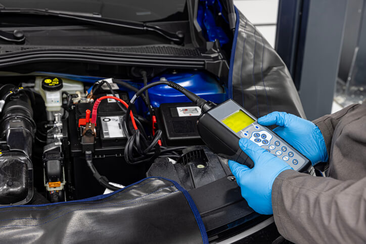
1) Battery/starting/charging snapshot
What’s the easiest first scope test for beginners? Battery/starting/charging testing is practical, often non-invasive, and immediately useful because it evaluates performance under real load conditions, cranking and charging, rather than relying on static checks.
A typical workflow uses a voltage connection at the battery and (where appropriate) a current clamp around the main ground/negative cable. The goal is to see the system behave in the conditions where failures actually happen: cranking voltage drop, starter demand, charging recovery, and stability under electrical load.
What you learn from this test is bigger than just battery health. You learn how to capture slow events and fast transients in a controlled way, how to interpret “healthy vs stressed” under load, and why scan data alone is often not enough to diagnose starting and charging complaints.
2) Alternator ripple check
Charging issues are often “almost okay” until load increases, and alternator ripple is one of the most accessible patterns to learn because it’s repeatable and visual. The core concept is that alternator output contains a ripple pattern due to rectification and the way the alternator produces and converts current.
When ripple becomes abnormal, you may see disruptions such as missing sections of the pattern or sharp spikes that stand out from the normal structure. The real learning value here is that this is a waveform where shape consistency matters. You’re training your eye to recognize a healthy repeating pattern and to validate changes under different electrical loads.
3) Crank/cam correlation as a timing truth test
This is the first “two-channel thinking” test every diagnostic technician should learn, and it’s a major reason people search for crank/cam correlation. It can be a non-intrusive way to validate timing relationships and sensor phasing without immediately disassembling the engine.
The basic approach is straightforward: capture crankshaft position and camshaft position signals at the same time (using OEM information to identify the correct signal circuits), then compare their relationship. Because engine control depends on accurate speed and position reference data, timing discrepancies, whether from mechanical timing concerns, sensor alignment, or signal integrity, can show up as an offset or inconsistency in how the signals align.

The real skill you’re building here isn’t just capturing the waveforms. It’s learning to express timing in a diagnostic way: describing offsets and alignment clearly (often in degrees or teeth, depending on the signal and tooling) and comparing against known-good patterns or manufacturer data instead of guessing.
4) Injector control and current analysis
Injector testing is a strong bridge skill because it forces you to connect scan-tool clues (misfire counters, fuel trims, DTCs) to the control signal and real injector behaviour. With an automotive oscilloscope, you can evaluate whether the injector is being commanded correctly and whether the control pattern is consistent with how that system operates.
This is especially useful on systems where control strategies can include rapid changes during the opening phase and different control behaviour during the hold phase. Scope-based injector evaluation helps you avoid expensive trial-and-error by confirming whether the issue is likely electrical (open/short/resistance/driver behaviour) or whether you need to move toward mechanical fuel delivery checks and additional testing.
Because injector circuits can differ significantly between technologies and vehicle platforms, treat guided tests and general waveform examples as structured starting points, not definitive procedures. Always verify with OEM information and follow safe probing practices.

5) Ignition primary voltage and current
Ignition is where intermittent faults, poor grounds, and load-dependent breakdowns often hide. It’s also one of the best places to apply comparison tools, because ignition events are repetitive and should look consistent when the system is healthy.
A practical early method is to capture repeated ignition events at idle and under load (when safe and appropriate), then evaluate consistency from event to event. This is where overlay-style review is extremely useful: healthy patterns tend to stack cleanly, while intermittent misfire behaviour can appear as outliers affecting only one or two events.
Building Real Diagnostic Confidence
Scope proficiency grows fastest when you practise on systems you’ll see in almost every bay. Battery/starting/charging captures teach you load testing and capture control. Alternator ripple teaches pattern recognition. Crank/cam correlation teaches two-channel timing logic. Injector and ignition testing build your ability to diagnose control signals and repetitive events with consistency checks.
The key is to develop a routine: capture, measure, compare, and confirm. That workflow is what turns an automotive oscilloscope from “a waveform machine” into a diagnostic tool you can trust. These diagnostic competencies align with the Red Seal Automotive Service Technician occupational standards, which outline electrical testing and signal analysis as core trade skills in Canada.
If you’re serious about building diagnostic confidence, the fastest progress comes from structured, hands-on learning. An auto mechanic training course can help you develop the electrical fundamentals, testing habits, and shop workflow that support modern scope-based diagnosis.
Start training in an Auto mechanic school in Surrey and prepare for a career built on skill, precision, and opportunity.
Contact us today to learn more about our auto mechanic courses!
Key Takeaways
- An automotive oscilloscope provides real-time electrical evidence beyond scan tool data.
- Battery/starting/charging captures are ideal beginner scope tests.
- Alternator ripple testing builds waveform pattern recognition skills.
- Crank/cam correlation validates timing relationships without disassembly.
- Injector and ignition testing help confirm control signal integrity.
- Always measure and compare waveforms instead of guessing.
FAQ
Q: When is a scope better than a scan tool?
A: A scope is better when you need to see what a circuit or component is actually doing in real time, especially for load-dependent and intermittent electrical faults that may not set a code.
Q: What’s the easiest first scope test for beginners?
A: Battery/starting/charging testing is practical, often non-invasive, and immediately useful because it evaluates performance under real load conditions, cranking and charging, rather than relying on static checks.
Q: How do you avoid misreading waveforms?
A: Avoid misreading waveforms by measuring and comparing instead of guessing. Use measurements (frequency, duty cycle, pulse width), compare against a known reference waveform, and use overlays to isolate intermittent outlier events in repetitive patterns.
