
Automotive Diagnostics Workflow: Scan Tools, Live Data, and Smarter Repairs
TL;DR: A smart automotive diagnostics workflow is simple: verify the concern, scan for diagnostic trouble codes, use freeze frame + scan tool live data to build a test plan, confirm the fix, and document results. This approach helps you avoid parts swapping and build confidence in real no-start and battery-drain complaints.
Modern vehicles don’t just “break”—they report clues. The technicians who stand out are the ones who can turn scan data into a clear test plan, then prove the repair is fixed.
This guide gives you a beginner-friendly automotive diagnostics workflow you can use on common issues, without guessing.
The Automotive Diagnostics Workflow That Works: Verify → Scan → Test → Confirm
What’s the best beginner-friendly diagnostic sequence (verify, scan, test, confirm)?
A reliable sequence is:
- Verify the concern (what exactly happens, when, and how often).
- Scan modules, record diagnostic trouble codes, freeze frame, and readiness/monitor info. ASE training standards emphasize retrieving and recording DTCs and freeze frame data, then using service info for step-by-step diagnosis.
- Test the most likely causes with evidence (not guesswork).
- Confirm the fix (recheck data, road test, and verify the symptom is gone).
That’s the backbone of real diagnostic thinking.
Step 1: Verify (and Don’t Skip the Basics)
As ATC Cambridge’s auto mechanic training practical learning emphasizes, verify the root causes. Before you plug in a scan tool, confirm:
- Is it crank-no-start or no-crank?
- Battery state, connections, and obvious damage
- Fluids, vacuum hoses, intake ducting, and loose connectors
This prevents you from chasing codes that are “symptoms,” not root causes.
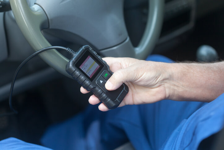
Step 2: Scan (DTCs + Freeze Frame + Live Data)
OBD2 diagnostics are standardized for emissions-related systems, and they store information to help technicians find and fix problems.
When scanning, capture:
- Diagnostic trouble codes (DTCs) (confirmed + pending when available)
- Freeze frame (a snapshot of conditions when a code set)
- Scan tool live data (what the vehicle is doing right now)
Scan tool “modes” (like Mode $01 live data and Mode $02 freeze frame) are defined under SAE J1979 (ISO 15031-5), and many scan tools present them behind the scenes.
Pro tip: Don’t clear codes at the start, as clearing can erase valuable data like freeze frame and reset monitor status.

Step 3: Decode What DTCs Are Telling You
As ATC Cambridge auto mechanic school teaches, DTCs follow a standardized structure (SAE J2012 / ISO 15031-6).
At a high level:
- P = Powertrain, B = Body, C = Chassis, U = Network/communications
- “Generic” vs manufacturer-controlled ranges exist (important when looking up info).
Use codes to form a test plan, not a shopping list.
Step 4: Test With Evidence (Avoid “Parts Swapping”)
How do you avoid “parts swapping” and diagnose with evidence?
You avoid guessing by proving each step:
- Use live data to see what’s missing (fuel, spark, air, RPM signal, voltage, network comms)
- Confirm power/ground and signal integrity before replacing components
- Check service information and bulletins first—ASE-aligned training emphasizes using service info and step-by-step troubleshooting.
If you can’t explain why a part failed your test, pause and test again.
Two Common Examples
Example A: No-start diagnosis (quick structure)
A practical no-start process often moves from spark → fuel → compression, depending on symptoms and scan results.
- If it’s cranking but not starting: scan for DTCs, verify spark, verify fuel delivery, then confirm mechanical integrity (compression)
- Freeze frame (when present) can help you reproduce conditions that triggered the fault.
Example B: Parasitic draw test (battery drain)
A solid parasitic draw test starts only after the vehicle’s modules “go to sleep,” which can take 30–120 minutes depending on the vehicle.
A common diagnostic approach is measuring voltage drop across fuses to identify which circuits are still drawing current, then isolating components on that circuit.
(Always confirm the acceptable draw spec using service info—varies by model.)

Step 5: Confirm and Document (This Is Where Pros Separate Themselves)
How do you document a diagnostic process for employers/customers?
Write it like a story with proof:
- Concern verified: yes/no + conditions
- Scan results: DTCs + freeze frame highlights
- Tests performed: what you tested and what you observed
- Repair and verification: what changed after the fix (live data, road test, no return codes)
ASE-aligned guidance repeatedly emphasizes recording DTCs, using scan data, clearing codes when directed, and verifying the repair.
Build These Skills Faster (Training Matters)
If you want to sharpen diagnostic thinking with structured practice, explore hands-on training that includes modern electrical diagnostic processes.
When you’re ready to take the next step and become a mechanic, strong automotive diagnostics is one of the fastest ways to stand out early.
Key Takeaways
- Automotive diagnostics is a repeatable workflow, not a guessing game.
- Start with Verify → Scan → Test → Confirm to stay efficient and accurate.
- Use diagnostic trouble codes + freeze frame + scan tool live data to build a test plan.
- Strong documentation proves value to employers and customers.
- No-start and parasitic draw complaints become manageable with a consistent method.
FAQ
Q: What’s the best beginner-friendly diagnostic sequence (verify, scan, test, confirm)?
A: A reliable sequence is:
- Verify the concern (what exactly happens, when, and how often).
- Scan modules, record diagnostic trouble codes, freeze frame, and readiness/monitor info. ASE training standards emphasize retrieving and recording DTCs and freeze frame data, then using service info for step-by-step diagnosis.
- Test the most likely causes with evidence (not guesswork).
- Confirm the fix (recheck data, road test, and verify the symptom is gone).
That’s the backbone of real diagnostic thinking.
Q: How do you avoid “parts swapping” and diagnose with evidence?
A: You avoid guessing by proving each step:
- Use live data to see what’s missing (fuel, spark, air, RPM signal, voltage, network comms)
- Confirm power/ground and signal integrity before replacing components
- Check service information and bulletins first. ASE-aligned training emphasizes using service info and step-by-step troubleshooting.
If you can’t explain why a part failed your test, pause and test again.
Q: How do you document a diagnostic process for employers/customers?
A: Write it like a story with proof:
- Concern verified: yes/no + conditions
- Scan results: DTCs + freeze frame highlights
- Tests performed: what you tested and what you observed
- Repair and verification: what changed after the fix (live data, road test, no return codes)
